FC, OSLO, and DTB types of evaporative crystallizers
Evaporative crystallizer definition: An industrial apparatus that achieves supersaturation of a solution by evaporating the solvent, thereby promoting the precipitation of solute in crystalline form. Evaporative crystallizers share identical equipment structure and operational principles with conventional evaporators used for solution concentration. They function by heating the solution to boiling, where solvent evaporation and vaporization concentrate the solution to a supersaturated state, facilitating crystallization and precipitation.
Evaporative crystallizers can operate under reduced pressure, enabling the maintenance of lower temperatures to achieve greater supersaturation in the solution. However, near the heating surface, solvent vaporization occurs rapidly, making it difficult to control the solution's supersaturation and consequently challenging to regulate crystal particle size. This type of crystallizer is suitable for applications where strict control over product crystal size is not required. This article primarily introduces the fundamental principles of evaporative crystallizers while providing detailed descriptions of three common types: the FC-type, OSLO-type, and DTB-type evaporative crystallizers.
II. FC-Type Evaporative Crystallizer
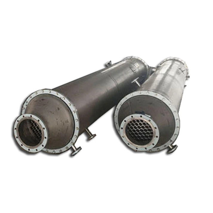
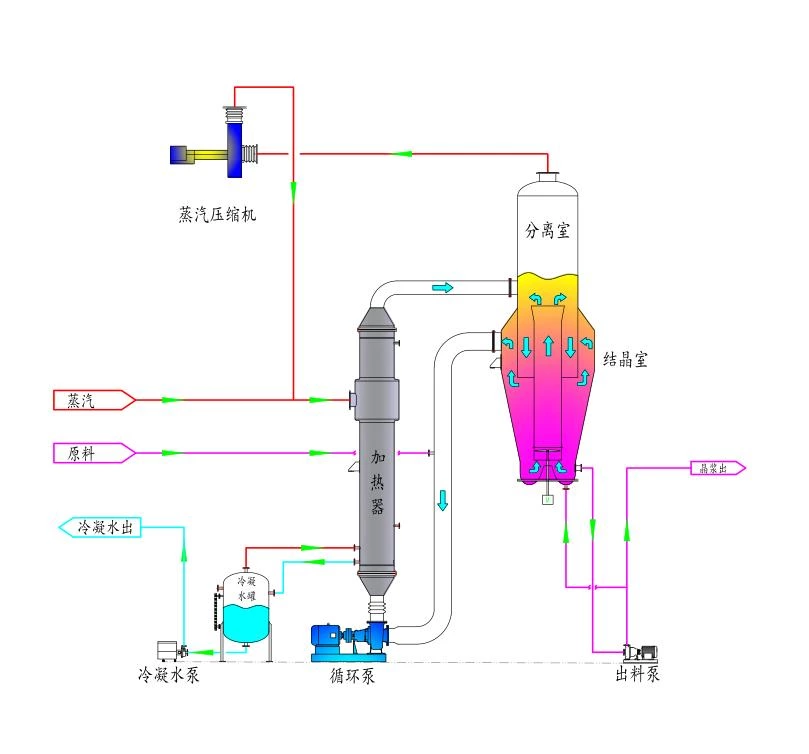
The FC-type evaporative crystallizer, fully known as the Forced Circulation evaporative crystallizer, is a highly efficient industrial crystallization device primarily used to treat wastewater containing dissolved solids or solutions generated during production processes. It crystallizes solutes (such as various salts) by evaporating the solvent. The FC Evaporator plays a vital role across numerous industrial sectors due to its high-efficiency evaporation and crystallization capabilities, excellent adaptability, and user-friendly operation. It serves as an effective solution for treating dissolved solids in wastewater and recovering valuable materials. Below is a detailed introduction to the FC Evaporator:
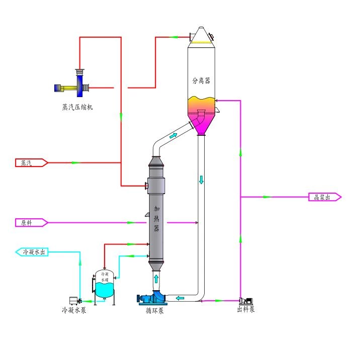
Features of the FC Evaporative Crystallizer
Forced Circulation: By using a pump to force the solution to circulate, heat transfer efficiency is enhanced while reducing the risk of scaling and clogging.
Crystal size control: The resulting crystals exhibit a small particle size, typically ranging from 0.15 to 0.3 mm, meeting the quality requirements for certain specific products.
Simple structure, easy operation: Designed with a focus on simplifying the structure for easy maintenance and operation.
Anti-clogging design: The evaporation crystallization chamber is positioned 4-6 meters above the heating chamber to prevent crystallization within the heat exchange tubes. Simultaneously, flow velocity within the circulation pipes is controlled to prevent pipe blockages.
Highly Adaptable: Widely applied in chemical, light industry, pharmaceutical, and other sectors, it is particularly suited for treating high-salinity wastewater and other challenging industrial effluents. While OSLO crystallizers and DTB evaporative crystallizers offer significant advantages in crystal particle size control, an increasing number of evaporative crystallization manufacturers prefer the simpler, user-friendly FC evaporative crystallizer for salt-containing wastewater evaporation and crystallization applications.
Operational Precautions
The height difference between the evaporation crystallization chamber and the heating chamber must be considered during design to ensure stable operation of the evaporation process.
The flow velocity in the upper circulation pipe must be lower than that in the lower circulation pipe to prevent violent boiling caused by bubble formation.
Maintain appropriate vacuum levels and temperature control to optimize evaporation efficiency and crystal quality.
Oslo OSLO Crystallizer
The OSLO crystallizer is a classic industrial crystallization device. With its unique design and high-efficiency performance, it is widely used in the food, pharmaceutical, and chemical industries, particularly suited for crystallizing materials with stringent requirements for crystal particle size. Also known as the Krystal crystallizer or particle size classification crystallizer, it was originally designed and developed by the Finnish OSLO Crystallization Company in the early 20th century.
The OSLO crystallizer consists of an evaporation chamber and a crystallization chamber. After being preheated by an external heater, the feed solution is rapidly evaporated within the evaporator. Solvent is removed while simultaneously providing cooling, causing the solution to rapidly enter the metastable zone and precipitate crystals. Its operation follows a typical mother liquor circulation process. The advantage lies in the circulation liquid containing virtually no crystal particles, thereby preventing excessive secondary nucleation caused by collisions between pump impellers and crystals. Combined with the particle size classification effect of the crystallization chamber, this results in large, uniform crystal particles. Its disadvantage is limited operational flexibility, as the mother liquor circulation rate is constrained by the settling velocity of product particles in the saturated solution. Furthermore, crystallization layers may form inside the heater, reducing the heat transfer coefficient.

Features and Advantages
Special structural design: Enables the production of crystals with large volume and narrow particle size distribution. High circulation volume and supersaturation control: A substantial solution circulation volume combined with moderate supersaturation minimizes secondary nucleation, facilitating continuous and stable crystal growth. Continuous Operation and High Yield: Supports continuous production modes, accommodates varying output scales, and offers substantial production capacity suitable for industrial manufacturing. Particle Size Grading: Internal crystallizer structures promote automatic grading of crystals by particle size, facilitating the production of uniform, high-quality products. Low Labor Intensity and Energy Efficiency: High automation reduces manual intervention, while certain designs (e.g., integrated MVR technology) effectively conserve energy. The OSLO crystallizer is particularly vital in applications requiring high-purity, large-particle crystals, such as pharmaceutical intermediates, fine chemicals, food additives, salt, and sugar crystallization processes. Its efficient, stable, and controllable crystallization process meets stringent crystal quality requirements across diverse industries.
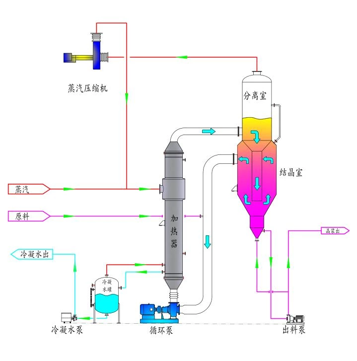
DTB Evaporative Crystallizer
The DTB-type evaporative crystallizer (Draft Tube Baffled Crystallizer) is a high-efficiency continuous crystallization device widely used in evaporation crystallization processes across multiple industries including chemical, food, and pharmaceutical. Its design features integrate a draft tube and baffles, hence the name DTB.
DTB (Deflector Tube and Baffle) Type Evaporative Crystallizer. Its key feature is a guide tube within the evaporation chamber, housing a propeller-equipped agitator that rapidly propels the saturated solution containing fine crystals toward the evaporation surface. Under vacuum conditions, the solvent undergoes flash evaporation, creating mild supersaturation. As the supersaturated liquid flows downward along the annular surface, it releases this supersaturation, allowing crystals to grow. A classification leg is positioned at the bottom of the vessel. The crystal slurry mixes with the raw material solution and circulates through the central flow guide pipe. Crystals precipitate within the classification leg once they reach a certain size. Simultaneously, the product undergoes washing, ensuring uniform crystal quality and particle size without fine crystal inclusions. The DTB evaporative crystallizer is a typical internal circulation crystallizer characterized by low supersaturation within the vessel, allowing the propeller to operate at low speeds. Due to its excellent performance, high production intensity, ability to produce large-grain crystalline products, and resistance to fouling, this type has become one of the primary configurations for continuous crystallizers.
Features and Advantages
High Efficiency: The DTB crystallizer enhances heat and mass transfer efficiency through its guide tube and baffle design, accelerating crystallization rates and making it suitable for large-scale continuous production. Controllable Crystal Quality: Crystal size, shape, and purity can be regulated by adjusting operating conditions such as temperature, pressure, and circulation rate. High Adaptability: Compatible with various crystallization systems including vacuum evaporation and vacuum flash cooling, while also suitable for reaction crystallization systems. Compact Structure: Despite its complex internal configuration, the overall design is space-efficient, facilitating maintenance and operation. Wide Application: Originally developed for potassium chloride production, its use has expanded across chemical, food, pharmaceutical, and other industries, demonstrating broad applicability and flexibility. In summary, the DTB evaporative crystallizer plays a vital role in industrial crystallization due to its high efficiency, flexibility, and controllability, making it a key piece of equipment for achieving efficient, high-quality crystallization processes.
Water Ring Vacuum Pump Overview: Working Principle, Operating Guidelines, Maintenance, and Troubleshooting
Water ring vacuum pumps are widely used in industrial sectors such as chemical engineering, petroleum, pharmaceuticals, food processing, sugar refining, and textiles. The 2BV water ring vacuum pump is a versatile liquid-circulating vacuum pump for rough vacuum applications. During operation, gas compression occurs isothermally. Therefore, when equipped with explosion-proof motors, it can safely compress and evacuate flammable and explosive gases. The 2BV series water ring vacuum pumps are single-stage liquid-circulating units with coaxial motor-pump design. All pump shafts feature mechanical seals, ensuring simple construction and easy maintenance.
As a widely used vacuum device, the water ring vacuum pump holds a significant position in industries such as chemical engineering, pharmaceuticals, and food processing due to its simple structure, stable operation, and ease of maintenance. This article will provide a detailed overview of the working principle, startup and operational procedures, shutdown steps, daily maintenance, and key inspection points for water ring vacuum pumps. It will also explore common malfunctions and their solutions, aiming to offer users comprehensive technical guidance and practical recommendations.
I. Working Principle of Water Ring Vacuum Pumps
Water ring vacuum pumps are primarily used to extract gases free of solid particles, thereby creating a vacuum within the system being evacuated. Their working medium is typically room-temperature water, though with appropriate material selection, they can also handle acids, alkalis, and other working fluids. The pump's core component is an impeller eccentrically mounted within the pump casing. Before startup, a certain height of working medium (e.g., water) must be injected into the pump. When the impeller rotates, the water is subjected to centrifugal force, forming a rotating water ring along the pump casing wall. The impeller and the side plates (also known as distributors) on both sides create a sealed chamber. During the first half of the impeller's rotation (passing through the intake port), the sealed chamber gradually expands, drawing gas in through the intake port. During the second half (passing through the exhaust port), the chamber gradually contracts, expelling gas through the exhaust port while carrying out a portion of water. This gas-water mixture is separated by a gas-liquid separator, allowing the water to be recycled.
II. Installation Notes
1. When installing a water ring vacuum pump, it must be placed horizontally on the ground and securely fastened through the anchor bolt holes.
2. When connecting pipes, take care to prevent particles such as welding slag from falling into the air intake.
3. The sealing gasket connecting the pipeline to the air intake should initially use a filter mesh (replace with a hollow sealing gasket after 24-48 hours of operation).
During operation, the motor converts electrical energy into kinetic energy to drive the water ring vacuum pump. This process generates heat with the water ring, while part of the circulating fluid is discharged from the pump along with the gas. Therefore, circulating fluid must be continuously supplied to the water ring vacuum pump during operation to replenish the fluid consumed within the pump and cool the circulating fluid inside, thereby meeting the pump's operational requirements.
III. Startup and Operation of Water Ring Vacuum Pumps Preparation Before Startup
1. Check rotor freedom of movement: Especially for pumps that have been unused for extended periods, manually rotate the coupling several times to ensure the rotor can turn freely.
2. Check oil level and condition: Ensure the lubricant level is normal and the oil is in good condition.
3. Fill with water to the appropriate level: Fill the water tank to approximately two-thirds full.
4. Close the intake valve: Ensure the intake valve is in the closed position.
5. Adjust the water supply valve: Open the pump water supply valve by 2-3 turns, then fine-tune based on actual conditions to minimize power consumption.
6. Test motor rotation direction: Before formal startup, test the motor individually to ensure correct rotation direction.
7. Turn on the power switch: Activate the power supply. Once the pump reaches its ultimate vacuum, open the valve on the intake line to initiate normal operation.
8. Monitor water temperature and mechanical seals: Adjust the water tank temperature promptly to ensure it does not exceed 40°C. Inspect the mechanical seals to ensure they are operating normally with no dripping or leakage.
9. Monitoring Abnormal Sounds: If cavitation noise is heard under ultimate vacuum conditions but power consumption remains low, this is normal. However, if abnormal sounds occur alongside increased power consumption, it indicates pump failure and requires immediate shutdown for inspection.
IV. Shutdown Procedure for Water Ring Vacuum Pumps
1. Close the intake valve: Ensure the intake valve is fully closed.
2. Close the water supply valve: After water supply is stopped, do not immediately shut off the pump. Allow the pump to continue running for 1-2 minutes to discharge some of the working fluid.
3. Turn off the motor switch: Finally, turn off the motor power supply.
V. Daily Maintenance of Water Ring Vacuum Pumps
1. Regularly inspect mechanical seals: Check the sealing condition to ensure the mechanical seal operates normally without leakage. If leakage occurs, replace it promptly. The replacement cycle for mechanical seals shall not exceed 5000 hours.
2. Monitor vacuum gauge readings: Regularly check whether the vacuum gauge readings, oil level, pump vibration, and noise are normal.
3. Check bearing temperature rise: The operating temperature of the pump bearings must not exceed the ambient temperature by more than 35°C, and the measured temperature must not exceed 70°C. The bearing chamber should be filled with grease to 2/3 of its capacity. Replace the lubricant 3-4 times annually and clean the bearings.
4. Keep the water tank clean: Ensure no foreign objects are present inside the tank to prevent impurities from entering the pump body and affecting its performance.
5. Inspect the circulating fluid for scaling. If the circulating fluid is hard water, perform periodic volumetric cleaning.
VI. Maintenance Procedures for Water Ring Vacuum Pumps
1. Remove the guard and motor: Loosen the motor bolts, release the motor set screw, and move the motor toward the pump to slacken the belt (for pumps with coupling drives, disconnect the coupling).
2. Removing the Pulley: Remove the V-belt, loosen the pulley locking bolts, tap the tapered sleeve to loosen the pulley, wedge a flat chisel into the tapered sleeve's gap, pry the sleeve open, and pull it out.
3. Disassemble the bearing: Remove the bearing cover and locking bolts, loosen the bearing bracket, and use a jacking screw to lift out the entire bracket and bearing assembly.
4. Disassembly of the Pump Housing: Loosen the inlet and outlet flanges, remove the pump tie bolts and anchor bolts. Gently tap the end cover with a copper rod to separate it from the pump housing, then slide the end cover out horizontally.
5. Rotor Disassembly: Remove the cylinder body, secure the rotor, remove the bearing cover and thrust bearing nut at the opposite end, extract the thrust bearing, remove the bearing bracket, and use a jacking screw to push out the bearing along with the bracket.
6. Clean and inspect all components:
Clean the rotor, disc, and both end caps. Clear the return holes and clean the check valve. Replace if worn or damaged.
Inspect the impeller for wear and corrosion, and replace it if necessary. Measure the shaft deflection to ensure it is less than 0.05 mm at the shaft center.
Inspect the disc surface to ensure no rust spots, cracks, or pitting, with a surface roughness ≤ Ra 1.6.
Confirm that the bearings are free of pitting, scars, or burrs, with a radial clearance ≤0.03mm after assembly.
Inspect the mechanical seal's verticality, radial clearance, gasket thickness, and compression to ensure compliance with requirements.
Ensure the parallelism between the motor pulley and the vacuum pump pulley is 0.4 mm.
Ensure the clearance between the impeller and the disc is 0.4–0.5 mm.
VII. Common Faults and Troubleshooting Methods
1. Insufficient air extraction
• Causes: Excessive clearance, air leakage, high water ring temperature, air leakage in the piping system.
• Remedial actions: Adjust clearances, repair air leaks, reduce water ring temperature, inspect piping system.
2. Vacuum level decreased
• Causes: Air leakage in the piping system, mechanical seal leakage, excessive clearance between the impeller and housing, insufficient water flow, or overheating of the water ring due to friction-induced heat in components.
• Remedial Actions: Repair leak points, adjust mechanical seals, adjust clearances, replenish water supply, reduce friction-induced heat generation.
3. Vibration or Noise
• Causes: Foreign objects causing friction inside the pump, blade detachment, cavitation, loose fasteners.
• Remedial actions: Remove foreign objects, replace blades, eliminate cavitation sources, tighten loose fasteners.
Conclusion
As a highly efficient and reliable vacuum device, water ring vacuum pumps require strict adherence to relevant specifications and technical requirements for selection, operation, maintenance, and repair. Enterprises should conduct comprehensive assessments based on their specific needs to select the most suitable equipment, and perform regular maintenance and repairs to ensure long-term stable operation, thereby enhancing production efficiency and product quality.