Structure of Shell-and-Tube Heat Exchangers and Repair Methods for Common Failures
The installation and repair of heat exchangers are common challenges encountered by many chemical engineers in actual production. Today, we will share the structural configurations of shell-and-tube heat exchangers and repair methods for common malfunctions.
Installation Knowledge for Shell-and-Tube Heat Exchangers
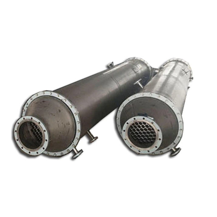
Shell-and-tube heat exchangers are the most widely used type of heat exchanger in chemical production. They feature a relatively simple structure, high heat transfer efficiency, and strong adaptability (capable of operating under high or low temperatures, as well as high or low pressures).The primary structure of a shell-and-tube heat exchanger consists of a bundle of tubes arranged in parallel within a cylindrical shell. Flanges are fitted to both ends of the shell, connecting the end caps to the shell body via bolts.
Small flanges for the inlet and outlet of the two media are provided on the shell and end cover respectively, facilitating corresponding pipeline connections.
Common shell-and-tube heat exchangers used in chemical production include fixed tube sheet, floating head, U-tube, and shell-type with thermal compensation functions. The primary structural components of fixed tube sheet shell-and-tube heat exchangers are: heads; heat exchange tubes; baffles; shell; supports; tube sheets.
The tube sheet (also known as the perforated plate) forms a non-detachable fixed connection with both ends of the shell. The ends of the tubes are connected to the tube sheet using expansion welding. To alter the flow direction of the medium between the tubes and enhance heat transfer efficiency, several baffles are installed on the inner wall of the shell. The end covers at both ends are connected to the shell via flanges.Two distinct media flow within the tubes and between the tubes, respectively. To enhance the heat transfer efficiency of the exchanger, partitions are sometimes installed within the heads to form fluid distribution chambers, thereby creating what is known as a double-tube shell-and-tube heat exchanger or a four-pass shell-and-tube heat exchanger.
Preparation Before Installation
Thorough preparation prior to heat exchanger installation ensures smooth execution of the installation process, enables achievement of all technical specifications, and guarantees installation quality.
1. Site Preparation for Construction Based on the site layout plan, conduct a thorough survey of all site conditions. Measure and determine transportation routes, parking locations, unloading points, and assess whether surrounding environments may impact equipment transportation and installation. Coordinate with relevant parties to meet lifting operation requirements. Clear transportation routes, ensuring roads are level and solid to allow vehicles to pass smoothly and safely deliver heat exchangers to the site. Installation width must meet installation requirements.
2. Carefully inspect the heat exchanger equipment against its drawings, including model, weight, geometric dimensions, pipe port orientation, and technical specifications. Review technical documentation such as factory certificates of conformity, manuals, and quality assurance certificates. Check for any damage or missing components (including shims, bolts, gaskets, and accessories). Maintain detailed inspection and acceptance records.
3. Foundation Acceptance Prior to heat exchanger installation, the foundation must undergo thorough inspection and handover acceptance. The foundation contractor shall submit quality certificates, survey records, and relevant construction technical documentation. The foundation shall feature clearly marked elevation lines and longitudinal/transverse centerlines. The foundation surface must be thoroughly cleaned, and any defects shall be addressed.
4. Lifting Preparation The lifting department shall prepare all lifting equipment and rigging, including cranes, derricks, wire ropes, pulley blocks, chain hoists, and shackles, and conduct thorough inspections in accordance with safety regulations. For large heat exchangers, due to their substantial diameter, numerous heating tubes, and heavy lifting weight, the lifting points should be selected at locations with reinforced backing plates on the shell supports. Additionally, wooden blocks should be placed on both sides of the shell to protect it from deformation caused by wire rope compression during lifting.
5. Prepare the Construction Plan To ensure orderly installation work, a construction plan should be prepared prior to installation. The plan should include the following components: preparation notes, basis for preparation, project overview, construction preparation, construction methods and measures, technical measures and requirements, construction tools, construction materials, personnel allocation, and a construction schedule chart.
Heat Exchanger Installation
1. Installation shall generally be performed in the following sequence and according to the following requirements.(1) Verify that dimensional deviations at all locations of the heat exchanger comply with standard requirements. (2) Embed sliding plates on the movable support side of the foundation. Shims must be placed on both sides of the anchor bolts. After equipment leveling, tapered shims may be welded to the equipment base plate but must not be welded to the underlying flat shims or sliding plates. All shims must be smooth and flat to ensure free expansion and contraction of the movable supports. (3) Install two tightened nuts on the anchor bolts of the movable support. Maintain a 1–3 mm gap between the nuts and the base plate to allow free sliding. (4) Permissible deviations after heat exchanger installation shall meet the following requirements: a. Elevation ≤ 3 mm b. Verticality (vertical units) ≤ 1/1000 and not exceeding 5 mm; Horizontality (horizontal units) ≤ 1/1000 and not exceeding 5 mm c. Center displacement ≤ 5 mm. (5) Piping connected to the heat exchanger shall be assembled under no load to avoid forced fitting and shall not impede thermal expansion of the heat exchanger. 2. Pressure Testing Pressure testing of heat exchangers (using fixed tube sheet type as an example) varies slightly by heat exchanger type. First, remove the heat exchanger heads and perform a hydraulic (typically water) test on the shell side. Upon reaching test pressure, in addition to inspecting the heat exchanger shell, focus on checking the connections between the heat exchange tubes and tube sheets (hereafter referred to as joints) for leaks at the expansion or welded joints. If minor leaks occur at a few joints, mark them accordingly. After depressurization, re-expand or re-weld these joints, then repeat the pressure test until satisfactory results are achieved. Following successful tube-side pressure testing, install the head with gaskets and conduct a tube-side pressure test. 3. Installation of Accessories After the heat exchanger is installed, aligned, leveled, and secured, proceed with the installation of piping, valves, and safety accessories. Refer to standard piping installation procedures for these components.
Maintenance of Shell-and-Tube Heat Exchangers
During operation, the most prone-to-failure component in shell-and-tube heat exchangers is the tubes. Factors such as media erosion and corrosion can damage the tubes. Therefore, regular inspections of the heat exchanger are essential to promptly identify faults and implement appropriate repair measures. The most common failures in shell-and-tube heat exchangers include tube wall scaling, tube leakage, and vibration. 1. Removal of Scale Deposits Scale readily forms on both the inner and outer surfaces of tubes due to prolonged exposure to the operating medium. Scale accumulation directly reduces heat transfer efficiency and must be addressed promptly. For removing scale from the inner tube surfaces, mechanical cleaning methods and chemical descaling can be employed.
2. Repairing Leaks The tube bundle of a shell-and-tube heat exchanger consists of numerous tubes arranged in a cluster. Erosion caused by the medium is the primary reason for tube leakage. Before repairing the tubes, a thorough inspection of the leakage condition must be conducted. Common methods for inspecting tube leaks include:
Install sampling ports at the low-pressure outlet end of the cooling water system to periodically collect and analyze cooling water samples. If the cooling water contains components of the cooled medium, it indicates leakage within the tube bundle. Subsequently, employ pressure testing to identify which tubes within the bundle are leaking. During inspection, first install a blind flange at one end of the tube bundle and submerge the bundle in a water tank. Then, using compressed air at a pressure not exceeding 1×100,000 Pa, test each tube port individually. If bubbles rise from the water tank when compressed air is introduced into a specific tube port, it indicates a leak in that tube, and the port should be marked accordingly. This method inspects all tubes. Based on the extent of damage, different repair methods are then applied.
Methods for Repairing Pipe Leaks
1. Repair Method for Minor Tube Leaks When only one or a few tubes in a tube bundle leak, and considering the minimal impact on the heat exchanger's efficiency, the leaking tubes can be repaired by plugging. Securely weld a conical metal plug at both ends of the tube to seal off the damaged section. The plug should have a taper angle of 3-5 degrees, with its larger end diameter slightly exceeding the inner diameter of the expanded tube section. 2. Repair Method for Multiple Leaking Tubes If numerous tubes leak, plugging them will significantly reduce the heat exchanger's efficiency (typically, plugged tubes should not exceed 10% of the total). In such cases, replace the tubes following these steps:
(1) Remove the leaking pipe
Pipe removal involves extracting the pipe from the tube sheet. For thin-walled non-ferrous metal pipes, removal can be achieved by drilling or reaming the hole, or by chiseling the pipe end. When using drilling or reaming methods, the diameter of the drill bit or reamer should match the inner diameter of the tube sheet hole. During drilling or reaming, the base metal of the expanded section within the tube sheet hole is removed, allowing the tube to be extracted. When chiseling, a pointed chisel can be used to contract the expanded tube end inward, disengaging the tube from the tube sheet and enabling its removal from the hole. For thick-walled tubes, oxygen-acetylene flame cutting can be employed. First, cut 2-4 notches in the expanded section, then hammer the tube end inward to retract it, disengaging the tube from the tube sheet opening. Subsequently, use a screw jack to push the tube out or extract it with a pulling tool. Regardless of the removal method used, both ends of the tube must be removed. Take care not to damage the tube sheet holes during removal to ensure a tight connection between the new tube and tube sheet when replacing the tube.
(2) Replace with new pipe and perform expansion jointing.
After the damaged tube is pulled out from the tube sheet, the new tube can be inserted into the hole in the tube sheet. The replacement tube should be of the same specifications and material as the original tube. When inserting the tube, align it with the corresponding hole in the tube sheet to ensure it is positioned correctly. The tube can then be connected to the tube sheet.